VIDEO TUTORIAL
Follow these steps and build your own ROBOHERO.
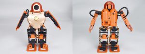
ROBOHERO BUILD YOUR OWN INSTRUCTION MANUAL
-
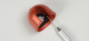
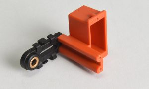
Copper bushing assembly
Parts list:
- copper lining x 14Pcs
- plastic part A x 1Pcs(L)
- plastic part B x 1Pcs(R)
- plastic part C x 2Pcs
- plastic part D x 2Pcs
- plastic part E x 2Pcs
- plastic part F x 2Pcs(L)
- plastic part G x 2Pcs(R)
Assembly method:According to the figure, press 14 pieces of copper bushings into the plastic parts
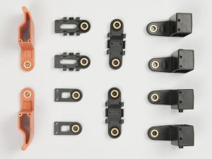 [Note] Please make sure that the copper bushing is pressed even so that no jut out on the appearance.
-
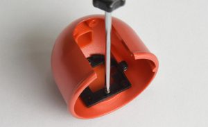
Front lampshade assembly
Parts list:
- plastic part H x 1Pcs
- plastic part I x 1Pcs
- lampshade paster x 1Pcs
Assembly method:According to the figure, press plastic part I into plastic part H and stick lampshade paster on plastic part I
 [Note] Please make sure that plastic part I is pressed in. You can add some glue in the juncture to prevent falling off.
 -
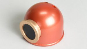
Hood assembly
Parts list:
- plastic part J x 1Pcs
- plastic part K x 1Pcs
- plastic part L x 1Pcs
- paster x 1Pcs
- HMJ2-6B x 2Pcs
- HMJ2-8B x 2Pcs
Assembly method:
- According to the figure, use HMJ2-8B to lock plastic part K into plastic part J
- Then use HMJ2-6B to lock plastic part L into plastic part K according to the figure
- Stick paster on plastic part L
-
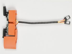
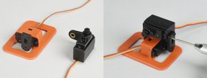
Servo assembly – environment setting
Parts list:
- Battery x 1Pcs
- Main control panel x 1Pcs
- Power board x 1Pcs
- Power connecting wire x 1Pcs
- Switching wire x 1Pcs
Assembly method:
- Respectively connect battery and switching wire to the power board and use power connecting wire to connect main control panel and power board
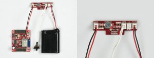
- Insert the servo needed setting into the corresponding position in the main control panel according to the number
- After turning on the power, download exclusive APP and after connecting WIFI and start the APP to operate servo setting function according to quick start guide
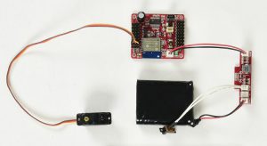
- Click ZERO, servo will automatically lock in the neutral point. At this time you can start assembling the axle sleeve and connecting base of servo
[Note]
- Please pay attention to the position of switch in case of putting the main control panel and charging panel in the place easy to cause short circuit or inflammable when turning on the power
- Pay attention to the direction when connecting the wire of servo and main control panel (black wire/negative terminal are all toward the outside of main control panel)
-
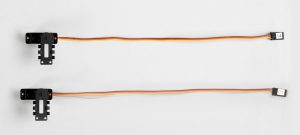
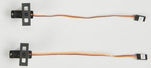
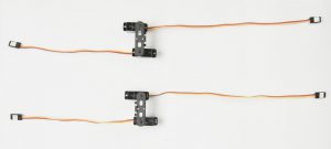
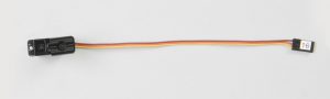
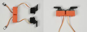
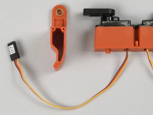
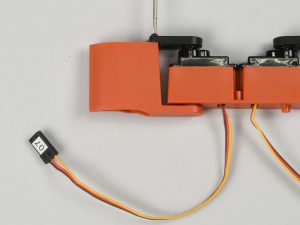
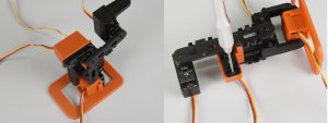
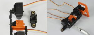
Servo assembly – axle sleeve and connecting base
Parts list:
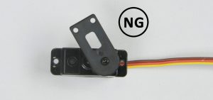
- servo x 1Pcs
- axle sleeve x 1Pcs
- HMF2-5B-1 x 1Pcs
- plastic part C1 x 1Pcs
Assembly method:
- Follow environment setting steps, use APP servo setting function, click ZERO, and lock servo needed setting
- Press axle sleeve into the servo gear
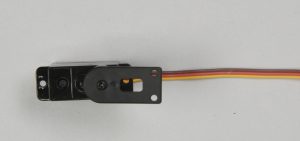
- Follow the servo’s connecting base angle setting, press the plastic part CI with correct angle into the axle sleeve and use HMF-5B-1 to lock in
[Note]
- Different servos have different connecting base angle setting. Please do not mix them together
- If the connecting base can not be adjusted to the required angle (90°or180°), you can take out the axle sleeve and rotate it to change its position before placing the gear, and then readjust the connecting base angle.
-
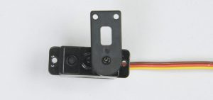
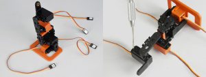
Servo assembly – setting
Parts list:
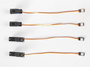
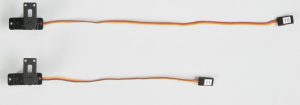
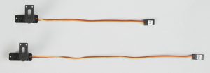
- servo x 17Pcs
- axle sleeve x 17Pcs
- HMF2-5B-1 x 17Pcs
- plastic part C1 x 8Pcs
- plastic part D1 x 2Pcs
- plastic part M x 2Pcs
- plastic part E1 x 2Pcs
- plastic part N x 1Pcs
Assembly method:
- Follow the axle sleeve and connecting base steps, respectively complete the setting and assembly of the 17 servos
- servo No.#6,#7,#8,#9’s connecting base angle (180°) setting is shown as below
- servo No. #11,#15’s connecting base angle (90°) setting is shown as below
- servo No. #0,#4 ’s connecting base angle (90°) setting is shown as below
- servo No. #1,#14 ’s connecting base angle (90°) setting is shown as below
- servo No. #5,#10’s connecting base angle (90°) setting is shown as below
- servo No. #2,#3,#12,#13 ’s connecting base angle (90°) setting is shown as below
- servo No. #16 ’s connecting base angle (180°) setting is shown as below
[Note]
- Different servos have different connecting base angle setting. Please do not mix them together
- During assembling, please make sure to follow the figures. Pay attention to the servo number and direction of part
- Servo’s wire has two types of length (15CM & 22CM), the length of No.#0,#1,#2,#13,#14,#15 is 22CM, the length of other 11 pieces is 15CM
-
Hand assembly
Parts list:
- servo set x 4Pcs(#6,#7,#8,#9)
- plastic part A set x 1Pcs(L)
- plastic part B set x 1Pcs(R)
- plastic part O x 2Pcs
- HMJ2-8B x 12Pcs
- binding x 2Pcs
Assembly method:
- According to the figure, install servo set(#6,#7) into plastic part O and use HMJ2-8B to lock in
- According to the figure, install plastic part A set (L) into servo set #7 port and use HMJ2-8B to lock in
- According to the figure, set in the binding to complete the left hand assembly
- The right hand assembly is based on the same procedure (install plastic part B set into servo set #8 port)
[Note] During assembling, please make sure to follow the figures. Pay attention to the servo number and direction of part. -
Leg assembly – joint connecting base- upper
Parts list:
- plastic part P x 2Pcs
- plastic part E set x 2Pcs
- HMJ2-8B x 4Pcs
Assembly method:
- According to the figure, connect plastic part P with plastic part E set and use HMJ2-8B to lock in
- Follow the same procedure to complete another set of joint connecting base- upper assembly
[Note] During assembling, please make sure to follow the figures. -
Leg assembly – joint connecting base- lower
Parts list:
- plastic part Q1 x 1Pcs(L)
- plastic part Q2 x 1Pcs(R)
- plastic part D set x 2Pcs
- HMJ2-8B x 4Pcs
Assembly method:
- According to the figure, connect plastic part Q1 with plastic part D set and use HMJ2-8B to lock in to complete the joint connecting base-lower (L)
- Follow the same procedure to complete another set of joint connecting base- lower(R) assembly
[Note] During assembling, please make sure to follow the figures. Pay attention to the direction of part. -
Leg assembly
Parts list:
- servo set x 8Pcs(#0,#1,#2,#3,#12,#13,#14,#15)
- joint connecting base -upper x 2Pcs
- joint connecting base -lower x 2Pcs(L,R)
- plastic part F set x 2Pcs
- plastic part G set x 2Pcs
- plastic part R1 x 1Pcs(L)
- plastic part R2 x 1Pcs(R)
- HMJ2-8B x 16Pcs
- HMJ2-6B x 12Pcs
Assembly method:
- According to the figure, install servo set (#0) into plastic part R1 and use HMJ2-6B to lock in
- According to the figure, install plastic part F set and use HMJ2-6B to lock in
- According to the figure, install servo set (#1) and use HMJ2-8B to lock in
- According to the figure, install joint connecting base – lower (L) and use HMJ2-8B to lock in
- According to the figure, install servo set (#2,#3) and use HMJ2-6B to lock in
- According to the figure, install plastic part G set and use HMJ2-8B to lock in
- According to the figure, install joint connecting base- upper and use HMJ2-8B to lock in to complete the left leg assembly
- Follow the same procedure to complete the right leg assembly
[Note] During assembling, please make sure to follow the figures. Pay attention to the servo number and direction of part.
-
Leg assembly – wire adjustment
Parts list:
- left leg set x 1Pcs
- right leg set x 1Pcs
- fixing sleeve x 2Pcs
Assembly method:
- According to the figure, adjust all servos of the left leg to their maximum angle, level the wire and reserve enough moving space before installing the fixing sleeve
- Follow the same procedure to complete the whole right leg assembly
[Note] Please reserve enough wire length to prevent the servo being interfered by the wire when moving. -
Body assembly – four limbs servo
Parts list:
- servo set x 4Pcs(#4,#5,#10,#11)
- plastic part S x 1Pcs
- HMJ2-8B x 8Pcs
Assembly method:According to the figure, install servo set into plastic part S and use HMJ2-8B to lock in.
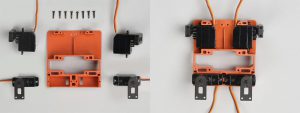 [Note] During assembling, please make sure to follow the figures. Pay attention to the servo number and direction of part.
 -
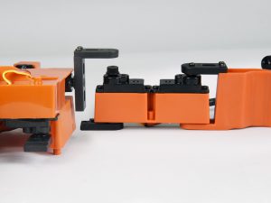
Body assembly – back
Parts list:
- plastic part T x 1Pcs
- HMJ2-8B x 4Pcs
Assembly method:According to the figure, install servo wire into plastic part T and use HMJ2-8B to lock in.
[Note]
- During assembling, please make sure to follow the figures. Pay attention to the servo number and direction of part
- Please make sure to arrange servo wire according to the figure
-
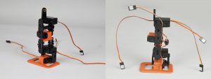
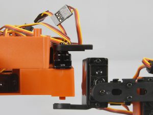
Body assembly – head servo
Parts list:
- servo set x 1Pcs(#16)
- HMJ2-6B x 4Pcs
Assembly method:
- According to the figure, install servo set and use HMJ2-6B to lock in
- According to the figure, put the servo wire through
[Note] During assembling, please make sure to follow the figures. Pay attention to the direction of part. -
Body assembly – joint connecting base
Parts list:
- plastic part C set x 2Pcs
- HMJ2-8B x 4Pcs
Assembly method:According to the figure, install plastic part C set and use HMJ2-8B to lock in.
 [Note] During assembling, please make sure to follow the figures. Pay attention to the direction of part.
 -
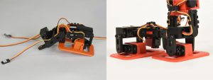
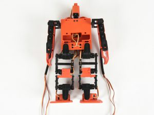
Four limbs assembly
Parts list:
- body set x 1Pcs
- left hand set x 1Pcs
- right hand set x 1Pcs
- left leg set x 1Pcs
- right leg set x 1Pcs
- HMJ2-6B x 4Pcs
- HMJ2-8B x 4Pcs
Assembly method:
- According to the figure, install left/right hand set and use HMJ2-8B to lock in
- According to the figure, install left/right leg set and use HMJ2-6B to lock in
[Note] During assembling, please make sure to follow the figures. Pay attention to the direction of part.
-
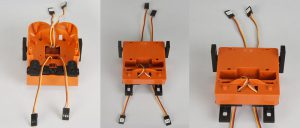
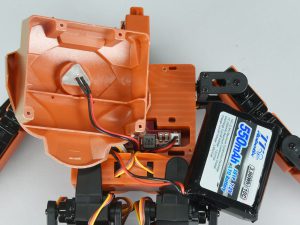
Power board assembly
Parts list:
- power board x 1Pcs
- power connecting wire x 1Pcs
- switching wire x 1Pcs
- charging socket cord x 1Pcs
- LED wire x 1Pcs
Assembly method:
- According to the figure, connect one terminal of the power connecting wire, switching wire and charging socket cord with power board and put the other terminal through the upper hole of the machine to the back
- According to the figure, put the socket terminal of the LED wire through the lower hole of the machine to the back and place the power board into the groove
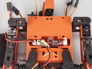
[Note] Please arrange the wire according to the figure for the convenience of subsequent assembly.
-
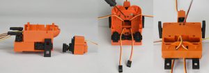
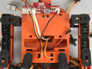
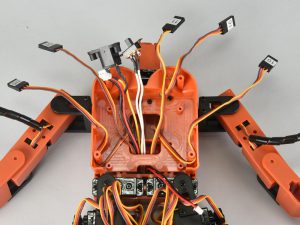
Main control panel assembly
Parts list:
- main control panel x 1Pcs
- HMJ2-6B x 4Pcs
Assembly method:According to the figure, put the power connecting wire, switching wire, charging socket cord, LED wire and left/right hand servo wire (#6,#7,#8,#9) to their fixed positions and then install the main control panel and use HMJ2-6B to lock in.
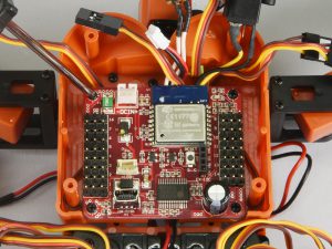 [Note] Before installing the main control panel, please pull out the wire according to the figure for the convenience of subsequent assembly.
 -
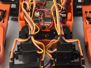
Main control panel connection
Assembly method:According to the figure, insert the power connecting wire, switching wire, charging socket cord, LED wire and 17 sets of servo wire into their corresponding positions in the main control panel.
[Note]
- Please pay attention to the direction when connecting the servo wire with the main control panel (black wire/negative terminal are all towards the outside of the main control panel)
- Please make sure that the servos are inserted into the corresponding positions in the main control panel according to the number
-
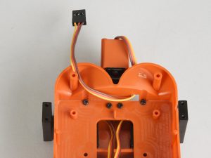
Arrange wires
Parts list:
- Binding belt x 2Pcs
Assembly method:Arrange the wire of main control panel according to the figure and reserve enough space for left/right leg servo wire (#0,#1,#2,#3,#12,#13,#14,#15) and then put them to fixed positions, use binding belt to fix them.
 [Note] Please reserve enough wire length in case of the servo being interfered by the wire when moving.
 -
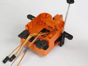
Back assembly
Parts list:
- plastic part U x 1Pcs
- HMF2-5B-1 x 2Pcs
- HMJ2-6B x 2Pcs
- HMJ2-8B x 4Pcs
Assembly method:
- According to the figure, install the charging socket cord into the charging hole in plastic part U and use HMJ2-6B to lock in
- According to the figure, install the switching wire into the corresponding position in plastic part U and use HMF2-5B-1 to lock in
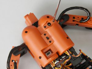
- According to the figure, install plastic part U set and use HMJ2-8B to lock in
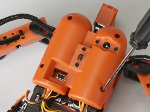
[Note]
- Please pay attention to the direction of the switching wire during assembling
- When assembling plastic part U, make sure that the hole of MINI USB is correct and meanwhile the wire should not be bended improperly
-
Front chest assembly
Parts list:
- battery x 1Pcs
- plastic part H set x 1Pcs
- HMJ2-8B x 4Pcs
Assembly method:
- According to the figure, connect battery to the power board
- According to the figure, install LED wire into plastic part H set
- According to the figure, install plastic part H set and use HMJ2-8B to lock in
[Note] Please make sure that the switch is in OFF before loading the battery. -
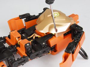
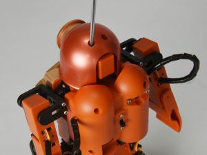
Head assembly
Parts list:
- hood set x 1Pcs
- HMJ2-6B x 2Pcs
Assembly method:According to the figure, install hood set and use HMJ2-6B to lock in.
-
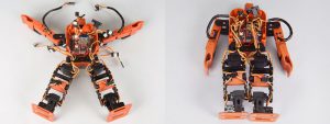
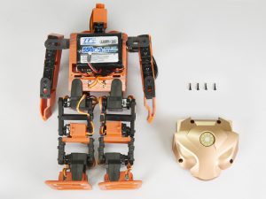
ROBOHERO assembly is done!